Figure 1:
Erratic ship positioning in Suez canal due to GPS jamming.

GPS/GNSS technology has revolutionized maritime navigation, providing accurate and reliable positioning information. However, the reliance on GNSS for ship navigation presents significant risks, particularly due to the potential for signal jamming and spoofing. These vulnerabilities can lead to serious navigational errors, with potentially damaging consequences.
The latest years, the threats posed by signal jamming and spoofing has dramatically increased in numbers and severity due to geopolitical tensions. GNSS signal disruption and manipulation is today playing a vital role as a warfare strategy in several conflicts around the world. Equipment to perform jamming and spoofing attacks is easily available. It is today equally easy for someone to carry out such attacks outside the known conflict areas.
GNSS is a navigation satellite used for two decades for military and commercial positioning and navigation. Today the following systems are available, providing signals for positioning and timing on a global basis:
One-meter accuracy is routinely achievable, and downtime events are extremely rare. Through international cooperation, these GNSS systems share common frequency bands, and affordable, multi-constellation navigation can be accomplished with a single receiver. The various signals are spaced close enough together to make reception efficient, but not so close as to interfere with each other.
All these GNSS systems share a common vulnerability as their signals are weak. GNSS satellites operate from Mid-Earth Orbit (MEO), approximately 20,000-25,000 km above the earth, to provide the best coverage and geometry for triangulation. As such, the transmitted signal is extremely weak upon arrival at the surface of the earth and makes GNSS navigation very susceptible to interference.
There are four main bands dedicated to Radio Navigation Satellite Service (RNSS), in which the GNSS constellations operate:
Jamming is the presence of a competing signal that prevents the GNSS receiver from decoding the authentic satellite signal. Jamming can be a result of an intentional act (like warfare) or sourced un-intentionally (direct or harmonic interference waves from electronics).
Spoofing is the intentional transmission of fake GNSS signals to divert users from their true position. Spoofing requires more sophisticated equipment to recreate the satellite signals. This technique is for example used in modern warfare to “capture” and mislead drones.
Several real-world incidents highlight the dangers of GPS jamming and spoofing in maritime navigation:
Baltic Sea (Fall 2024): Continuous GNSS disruption in a large area and scale causing serious challenges for shipping and aviation due to outages.
Suez Canal (Fall 2024): Continuous GNSS disruption in the area is present due to the geopolitical situations in the Middle East. See example below.
Schelder River, The Netherlands (2021): Strong GNSS jammer was accidently turned on at the Damen Shipyard in Vlissingen for a period of 2 hours. Analysis showed that 75% of all ships in the exposed area lost position in the period, disrupting the entrance to the Antwerp port.
Black Sea Incident (2017): Over 20 ships reported GPS anomalies in the Black Sea, with GPS receivers showing locations miles away from their actual positions. This incident is believed to be a result of GPS spoofing.
Port of Shanghai (2019): GPS jamming affected shipping operations in the busy Port of Shanghai, causing navigational disruptions and operational delays.
Strait of Hormuz (2019): Several ships reported GPS interference in the Strait of Hormuz, a critical chokepoint for global oil transportation, raising concerns about maritime security.
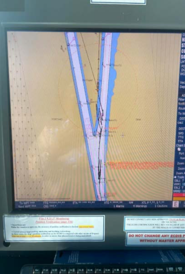
Figure 1:
Erratic ship positioning in Suez canal due to GPS jamming.
Figure 1 is an example from the Suez Canal in May 2024, showing erratic and potential damaging positioning of ship GNSS system while under exposure of signal disruption.
For years, AD Navigation AS has been at the front line addressing the vulnerability related to GNSS signal disruption. The result of this work was leading to the obvious need for test of equipment in a controlled jamming environment. In 2022 the first test bed was organized by Norwegian authorities in collaboration with international partners, including defence agencies and research institutions.

Figure 2
The main test area at the village of Bleik along with a close-up of one of the jamming antenna arrays purposely provided by the armed forces.
The jammer tests conducted at Bleik, Andøya (see figure 2), Norway, are significant events aimed at assessing the impact of GPS jamming on various navigation and communication systems. Andøya, with its remote location up north of Norway and controlled environment, provides an ideal location for these tests.

Figure 3
The participants. 300 people took part in the 2024 tests. Double compared to the 2023 tests.
The tests at Bleik are carried out over a period of five days, covering a vast variety of jamming/spoofing scenarios. Overall, the tests contain the following sequences:
During the tests, three different types of interference generators were used:
Low-power jammers of the type commercially available from the Internet
A high-power military-caliber jammer that could vary transmit power, frequency band and modulation
Signal generators with jamming and spoofing options also to include GNSS meaconing.
The low-power jammers were a mix of several different L1-only jammers, L1&L2 and L1&L2&L5/E6, all with relatively wide frequency bands and typical sweep modulations, except for one that used frequency hopping.
For the high-power jammer, two modulations were used, an unmodulated CW signal (the carrier of GPS L1) and a PRN signal (modulated carrier with C/A code from GPS satellite # 1, but without navigation message). During the tests, it was jammed in different combinations of modulations and frequency bands, whereupon the frequency bands used were L1, G1, B1l, L2, G2, L5 and E5b.
The spoofing attacks simulated GPS L1 C/A and Galileo E1 signals, running both incoherent and coherent attacks (ie, where the signals are not synchronized or are synchronized with real-time satellite data for the test position, respectively). Otherwise, the spoofing attacks were run in combination with jamming, both initial jamming attacks and jamming that were active while the spoofing was taking place (eg spoofing L1/E1 with jamming on G1, L2, L5).
All these attack possibilities were then used in different test setups, and for static and dynamic combinations of jammers and attack targets (participants). An example is motorcade tests with a jammer in one of the cars in the motorcade, or with a jammer stationary on the side of the road while the motorcade drove past.
Trials The Jammertest are organized with a strict program, incorporating several runs each day. Some of the runs were performed with a stable interference signal, and some were used dynamically, changing interference signals. The equipment ranged from low effect handheld jammers to high effect jamming in different combinations of the different frequency bands, including power-ramp tests (Figure 5).
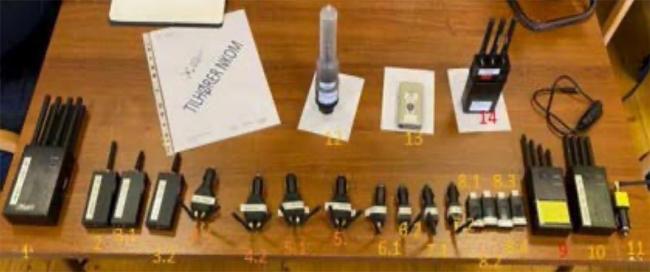
Figure 5
The variety of "commercially available" handheld jammers tested.
The trials were conducted around Bleik, and there were several areas which were available for the participants to conduct different types of tests. The entire test area is shown marked in red (Figure 5).
The village of Bleik and the surrounding area was the main testing area, marked in green. In addition, there was a “sandbox” for low effect jamming trials at Grundtvatn, marked in yellow (Figure 6).
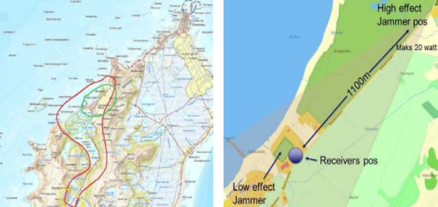
Figures 6 & 7
Entire test area marked in red.
Test area marked in green and yellow.
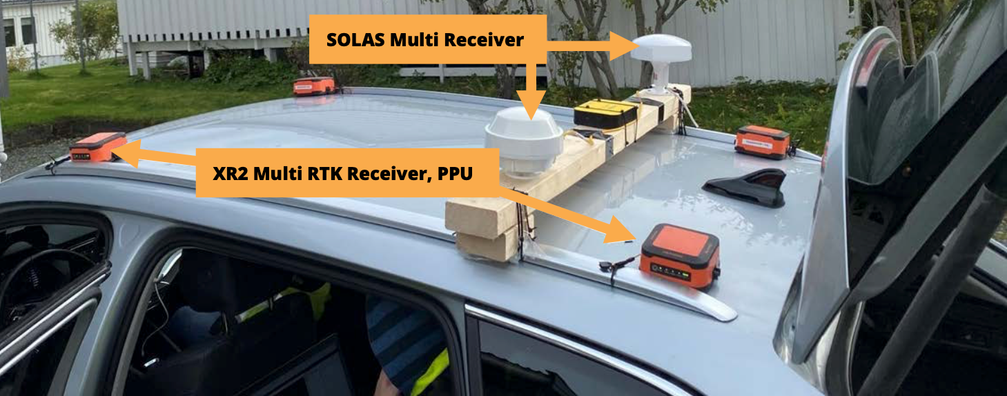
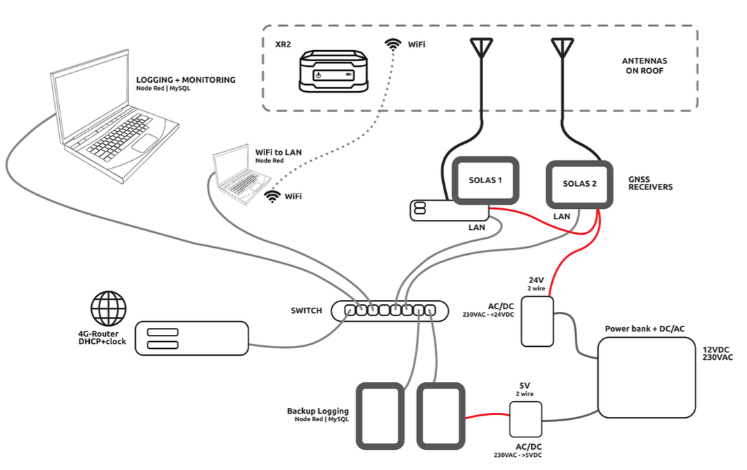
Figure 8: XR2 and SOLAS Setup.
A variety of tests have been carried out. Probably the most interesting test is the Ramp test. To investigate for a dependency on jamming power, ramp tests with increasing and decreasing jamming power were performed. In this, the receivers (and the car) are stationary and the distance to the jammer is constant at approximately 1100 m. The jammer used in this trial has a maximum power of 20 Watt, here shown for the L1, G1, L2 and L5 frequency bands.
The XR2 is generally performing better, never losing more than approximately 5 of its 32 satellites even during the highest intensity during this rather intensive jamming regimen. Generally, PNR jamming has a greater impact compared to CRW (continuous wave) jamming.
As displayed in Figure 9, during the PRN-ramp test, at around 1watt jamming from 1100 meters away, the jamming starts to affect both SOLAS receivers. More than 2 watts significantly reduce the performance, being all that is needed for the two SOLAS maritime receivers to lose position. The XR2 PPU is doing very good, producing reliable positioning throughout the entire test.
Also observed during the high effect jamming trials, it seems obvious that the Signal to Noise Ratio (SNR) determined for individual satellites is a good variable for warning for jamming incidents.
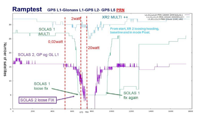
Figure 9: PRN-Ramp Test.
At the test site #2 a variety of tests involving low power jammer devices were performed. The aim is to discover how XR2 PPU with standard antenna configuration and standard SOLAS class GNSS system are performing under exposure of jamming signals from those easily available jammer devices.
The jammer location is about 300 meters from a public road. Various jammers were activated in accordance with the detailed test schedule. The test equipment was located in our test vehicle, and data logged for each sequence.
The typical observation is that XR2 PPU was unaffected when exposed of jamming signals from low power jammers, whereas SOLAS receivers stopped computing position under the exposure. SOLAS receivers were typically regaining positioning computation while the test vehicle moved out of the exposed area.
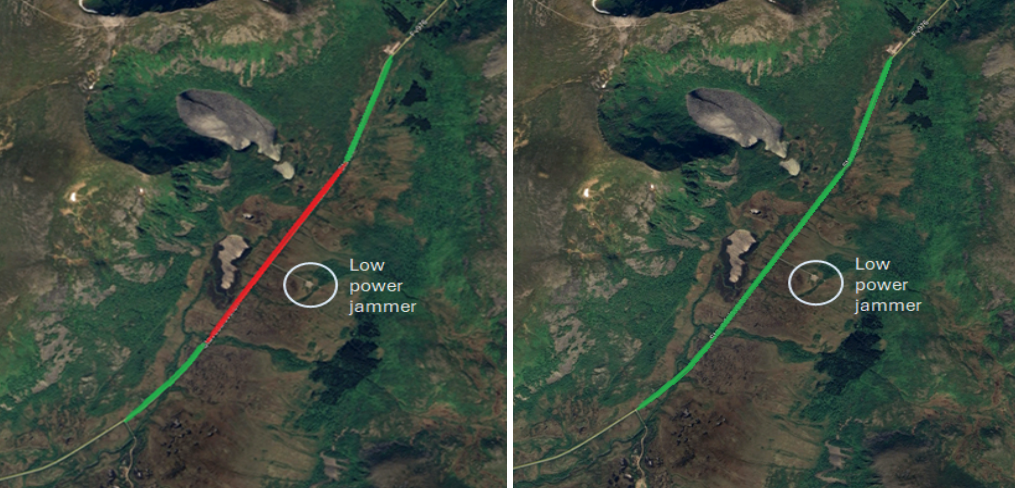
Figure 10: Low power jammer test.
Test site #1 also included a variety of tests involving high power jamming scenarios. The aim is to discover how XR2 core GNSS with advanced CRPA anti jamming antenna configuration and latest generation SOLAS class GNSS system are performing under exposure of jamming signals transmitted at 100 watts. This to expose the test system of a jamming signal up to 50dB. This test is simulated by the comprehensive jamming observed in areas with geopolitical tension. The jammer location was about 1500 meters from a public road (Figure 11). The test was performed by driving the test vehicle in and out of the exposed test area twice over a total period of 25 minutes.
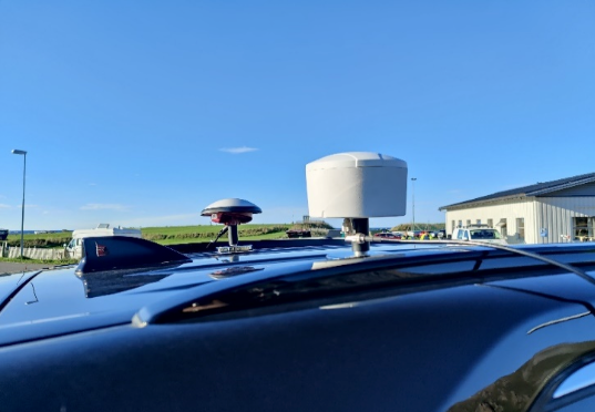
Figure 11
CRPA Antenna Used for High power jammer test.
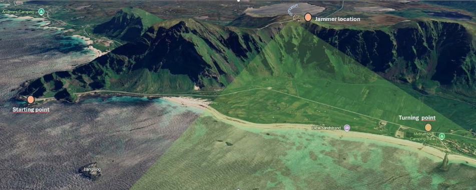
Figure 12: Jammer location
Figure 13 shows an overview of the number of tracked satellites as the test vehicle is moving in and out of the jamming area.
The CRPA antenna geared XR2 PPU is tracking 10-17 satellites throughout the entire test, even under exposure of the strong jamming signal. The two SOLAS receivers were tracking a total of approx. 30 satellites under normal tracking conditions but instantly dropping satellite tracking completely once inside the jammed area. The SOLAS receivers were quickly regaining sensible position once outside jamming area.
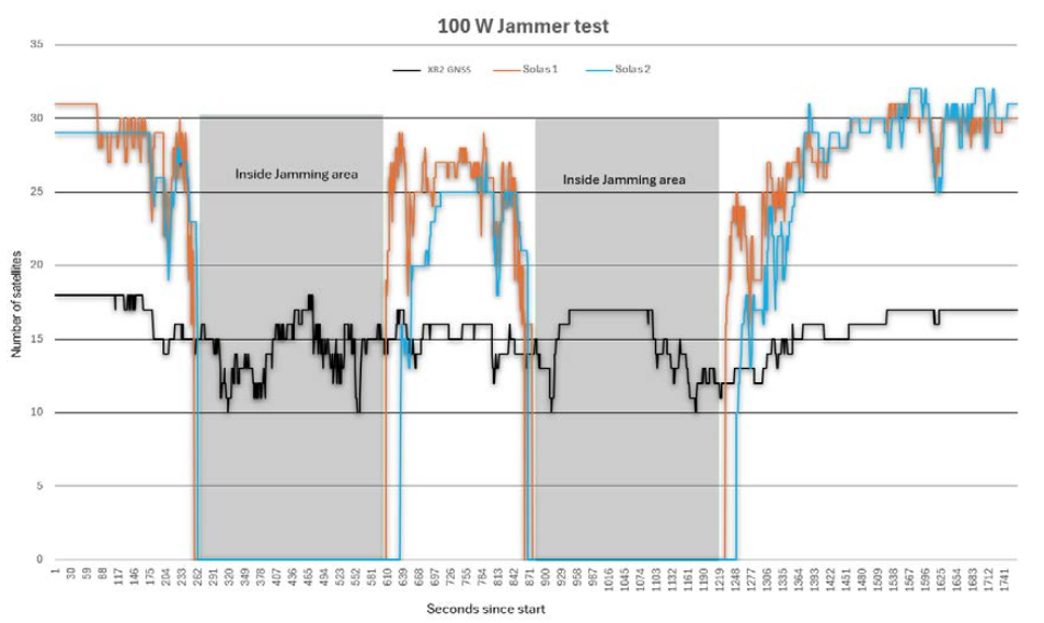
Figure 13: Number of tracked satellites
Utilizing the CRPA antenna is limiting the number of tracked satellite systems due to its design and advanced features, which is the trade-off to maintain reliable positioning under severe GNSS jamming exposure.
Test site #1 also included a variety of spoofing test scenarios. The aim is to discover how XR2 PPU with standard GNSS antenna configuration and latest generation SOLAS class GNSS system are performing when GNSS time messages are spoofed.
During first test, the time was shifted + 15 minutes along with a strong signal. XR2 PPU discovered the anomaly eventually and stopped computing position. XR2 PPU recovered quickly after test was over. The same behavior was observed for SOLAS2 receiver. However, SOLAS 1 receiver did not recover after test was over, as it crashed. The SOLAS1 receiver was requiring a total reset to fabric default configuration before it was working properly again. During second test, the time was shifted + 2 years along with a strong signal. XR2 PPU discovered the anomaly eventually and stopped computing position. XR2 PPU recovered quickly after test was over. The same behavior was observed for SOLAS1 receiver.
However, SOLAS 2 receiver did not recover after test was over, as it crashed. The SOLAS2 receiver was requiring a total reset to fabric default configuration as well as requiring new authorization files generated by manufacturer before it was working properly again. The current authorization files were corrupted during tests.
The core technology in XR2 PPU has been tested thoroughly during Jammertests in three consecutive test campaigns (2022, 2023 and 2024). Further tests of XR2 PPU will also commence in September 2025. The tests of XR2 PPU along with the SOLAS receivers has also been vetted by independent researchers from Norwegian Coastal Authorities. The findings from 2022 to 2024 are clear. SOLAS receivers were more vulnerable to interference compared to the XR2 PPU. Compared to each other, the SOLAS receivers performed to some extent more differently than was expected. At one time, one SOLAS receiver loses the position fix even though there are a lot of satellites in view and conditions seem OK, whereas other SOLAS receiver seemed stable.
The two receivers also disclosed a different time to recover after being jammed, where the one receiver came back at once after the influence was removed, and the other took a significant time to recover.
There seems to be different philosophies on how to respond after loss of fix. One SOLAS receiver continued to send the last known position with aging timestamp. The other SOLAS receiver stopped sending positioning data.
During test time spoofing sessions, SOLAS receivers crashed catastrophically requiring manufacturer support to recover.
XR2 geared with external CRPA antenna worked well during the entire week of testing and was unaffected during all the tests jamming and spoofing test scenarios.